

Hot tube fl aring system creates a standard tube fl are end by pressure forming and rapidly cooling the fl are form. The mobile TruFLARE™ system is ideal for production fl aring. It assures precise, concentric, repeatable tube flare connections. This is without requiring immediate assembly, which is often the case with other rudimentary hot fl aring systems.
KEY FEATURES
• Mobile and compact.
• 15’ long wand cable for added convenience.
• Repeatable tube fl ares.
• Allows fl aring in hard to reach places.
FlareLINK™ fi ttings, quality tube Flares and use of TruFASTEN™ torque wrenches ensure a leak-free assembly.
| Mobile TruFLARE™ Systems | |||
| Tube Material |
Mandrels Included |
Voltage | Part Number |
| PFA | 1/4”, 3/8”, 1/2”, 3/4”, 1” | 110 Volt | MTF416-110 |
| PFA | 1/4”, 3/8”, 1/2”, 3/4”, 1” | 220 Volt | MTF416-220 |
| PFA | 1-1/4” | 110 Volt | MTF20-110 |
| PFA | 1-1/4” | 220 Volt | MTF20-220 |
| PFA | 1-1/4”, 1-1/2” | 110 Volt | MTF20-24-40MM-110+ |
| PFA | 1-1/4”, 1-1/2” | 220 Volt | MTF20-24-40MM-220+ |
| FEP | 1/4”, 3/8”, 1/2”, 3/4”, 1” | 110 Volt | MTF416-110-FEP |
| FEP | 1/4”, 3/8”, 1/2”, 3/4”, 1” | 220 Volt | MTF416-220-FEP |
| PFA | 1/4”, 3/8”, 1/2”, 3/4”, 1” | 110 Volt | MTF416-110-P* |
| PFA | 1/4”, 3/8”, 1/2”, 3/4”, 1” | 220 Volt | MTF416-200-P* |
| *PTFE Mandrels | +special order | ||
GETTING STARTED
1 Select the PFA or FEP tube size to be fl ared.
2 Refer to Table 1 and 2 for the appropriate settings based on your tube size.
3 Set the Heat Temperature by pushing and holding the “HEAT TEMP” button and simultaneously pushing the “Up” or “Down” button to “Set Temperature.”
4 Set the Heat Time by pushing and holding the “HEAT TIME” button and simultaneously pushing the “Up” or “Down” button to “Set Time.”
5 Set the Cure Time by pushing and holding the “CURE TIME” button and simultaneously pushing the “Up” or “Down” button to “Set Time.”
FLARING
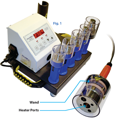
1 To begin fl aring insert the tube into the correct heater port located on the wand, see Fig. 1. Note: Push the tube into the correct heater port until it bottoms out.
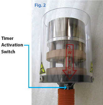
2 Once you insert the tube, push the timer activation switch on the wand. This will start the “Heat Cycle” timer. When the heat cycle is complete, an audible alarm will sound. Push the timer activation switch on the wand to turn off the alarm, see Fig. 2.
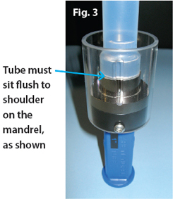
3 Remove the tube from the heater port and push onto the appropriate fl aring mandrel; hold for 5 to 10 seconds. Note: Tube must sit fl ush with shoulder on mandrel, see Fig. 3 (on back).
4 Once the tube is on the mandrel, push the timer activation switch on the wand to start the "CURE TIME." When the cure cycle is complete, an audible alarm will sound. Push the timer activation switch on the wand to turn off the alarm, see Fig. 2.
5 Remove the tube from the mandrel. Your new fl ared tube is ready for assembly.
6 During the fl aring process it is recommended to wear a gripping glove on the hand that is used to install the tube on the mandrel.
TROUBLESHOOTING
Creating Good Flares
When the tube is pushed onto the mandrel it must sit fl ush with the shoulder,
as shown in Fig. 3. If heated properly, tubing should sit fl ush to shoulder on the
mandrel. If it pushes back away from the shoulder you need to add “Heat Time”
in 5 to 10 second increments, until the tube sits on the shoulder.
| PFA Standard Tube | ||||
| Size | Wall Thickness |
Heater Temp |
Heat Time (Seconds) |
Cure Time (Seconds) |
| 1/4" | .047" | 2300 - 2700C | 20 - 70 | 50 |
| 3/8" | .062" | 2700C | 60 - 70 | 90 |
| 1/2" | .062" | 2700C | 70 - 80 | 120 |
| 3/4" | .062" | 2700C | 80 - 90 | 150 |
| 1" | .062" | 2700C | 80 - 90 | 150 |
| 1-1/4" | .075" | 2800C | 100 - 120 | 150 |
| 40 MM (1-1/2") |
2.29 MM (.090") |
2800C | 130 - 150 | 150 |
| table 1 | ||||
| FEP Standard Tube | ||||
| Size | Wall Thickness |
Heater Temp |
Heat Time (Seconds) |
Cure Time (Seconds) |
| 1/4" | .047" | 1600C | 15 - 20 | 35 - 40 |
| 3/8" | .062" | 1600C | 60 - 70 | 45 - 50 |
| 1/2" | .062" | 1600C | 70 - 80 | 45 - 50 |
| 3/4" | .062" | 1600C | 70 - 80 | 50 - 55 |
| 1" | .062" | 1600C | 70 - 80 | 55 - 60 |
| table 2 | ||||
info@fitlineinc.com ©Copyright 2014
Fit-LINE Inc. | 2901 Tech Center Drive | Santa Ana, CA 92705 | Phone: (714) 549-9091 | Fax: (714) 549-2778